Traceability in FPGA Design: Linking Requirements to Design and Test
Traceability in FPGA Design: Linking Requirements to Design and Test
Having well-defined requirements is important. But how do we know that every requirement has been implemented and properly verified?
In our previous article, Requirements Capture & Management for FPGA Projects, we discussed how to identify, structure, and manage FPGA requirements throughout the hardware development life cycle.
However, writing good requirements is only the beginning. As development progresses, requirements must be linked to the design elements responsible for implementing them and the verification activities used to demonstrate compliance.
This is where traceability becomes essential.
Traceability establishes relationships between requirements, design, and verification activities, allowing requirements to be followed from their origins through implementation and verification.
Although traceability applies to many engineering disciplines, this article focuses on how traceability can be established and maintained in FPGA development projects, using practical examples involving PLD requirements, RTL design elements, and verification test cases.
1. Why Is Traceability Important?
As an FPGA project grows, understanding the relationships between requirements, design elements, and verification activities becomes increasingly challenging. A single PLD requirement may affect multiple RTL modules, while one RTL module may implement several requirements.
Without traceability, identifying these relationships may require engineers to manually examine requirements specifications, HDL files, and verification procedures.
Well-established and maintained traceability allows engineers to answer questions such as:
- Which RTL modules or verification procedures would be affected if a particular requirement changed?
- Where in the hardware design is a specific system-level function implemented?
- What requirement or design decision justifies a particular hardware behavior?
- Which requirements are implemented by a specific HDL module?
- Have appropriate verification activities and supporting evidence been identified for every requirement?
Therefore, traceability is useful not only for documentation purposes but also for supporting design reviews, verification planning, debugging, and change impact analysis.
Traceability is particularly important in safety-critical development. For example, Objective CD-4 of AMC 20-152A explicitly addresses reviewing traceability between custom device requirements and detailed design for hardware Design Assurance Levels (DAL) A and B. The same objective does not impose an equivalent traceability review requirement for DAL C.
Nevertheless, maintaining links between PLD requirements and RTL design elements provides significant benefits even in FPGA projects where such traceability is not explicitly required.
2. Types of Traceability
Different types of traceability can be established in FPGA development, depending on the requirements, design elements, and verification records being linked.
Requirements-to-Requirements Traceability
This type of traceability establishes relationships between requirements at different levels of the hardware hierarchy.
For example:
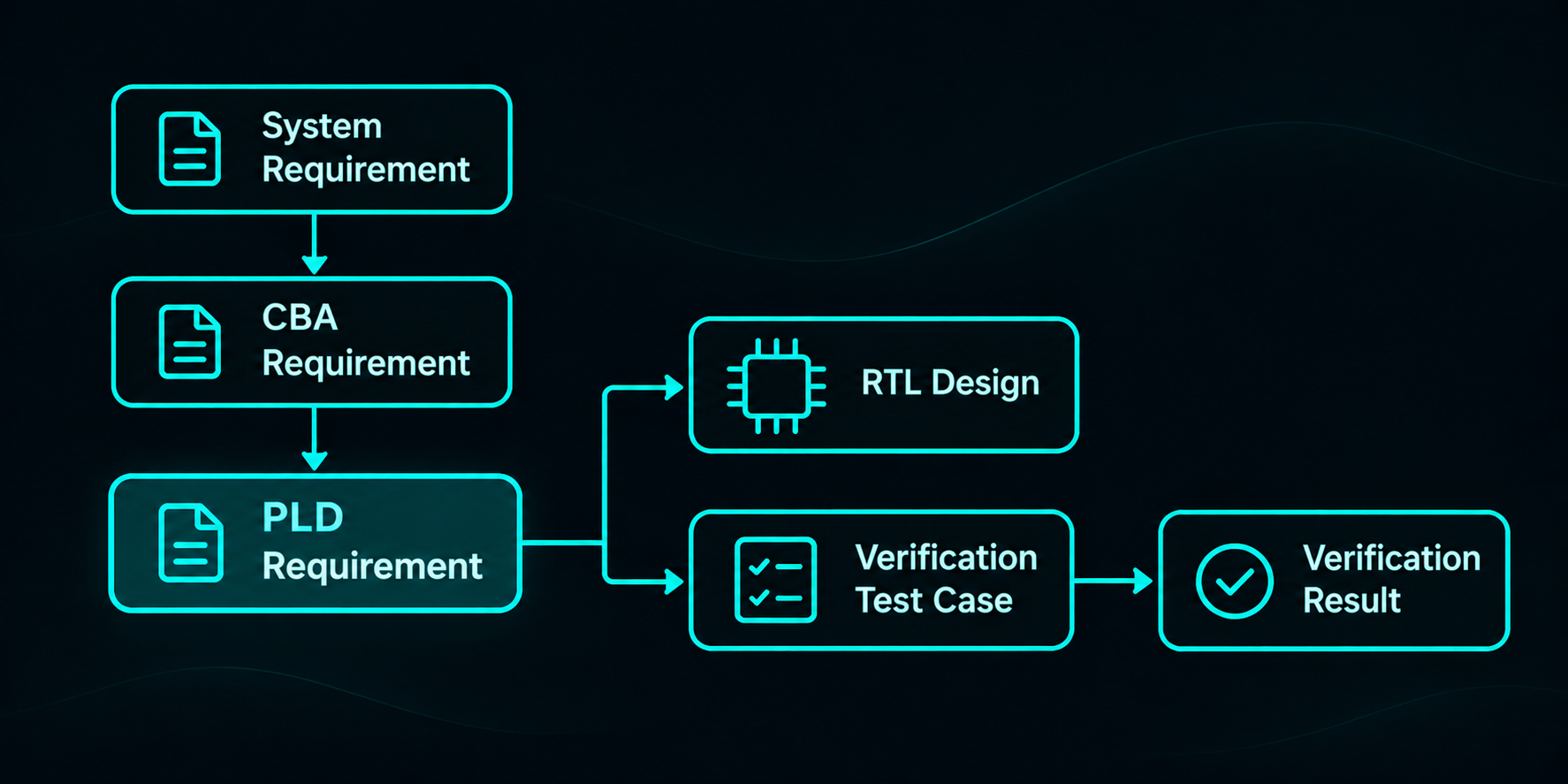
System Requirement → CBA Requirement → PLD Requirement
Higher-level requirements may be directly allocated to the PLD or refined and decomposed into more detailed PLD-level requirements. These relationships show how the functions assigned to the FPGA relate to higher-level needs.
Requirements-to-Design Traceability
Requirements-to-design traceability establishes relationships between PLD requirements and the RTL design elements responsible for implementing them.
PLD Requirement → RTL Design Element
This relationship allows engineers to identify where a particular requirement is implemented within the FPGA design.
Requirements-to-Verification Traceability
Requirements-to-verification traceability establishes relationships between requirements and the verification test cases and results used to demonstrate compliance.
PLD Requirement → Verification Test Case → Verification Result
These links allow engineers to track how requirements are verified and identify the corresponding verification evidence.
Requirements and Safety Assessment Relationships
In safety-critical projects, relevant hardware requirements may also be linked to safety assessment information.
In particular, derived requirements may need to be evaluated for their potential impact on system safety. The way these relationships are established depends on the project’s safety assessment and development assurance processes.
Forward and Backward Traceability
Traceability relationships should be traceable in both directions.
Forward traceability starts from a requirement and follows its relationships toward the relevant design elements or verification evidence.
Backward traceability starts from a design or verification record and identifies the requirement that justifies it.
Consider the following illustrative requirement:
PLD_REQ_020: When start_capture is sampled high at a rising edge of clk_100 while reset_n is high, the FPGA shall assert capture_active high on the next rising edge of clk_100, provided reset_n remains high.
The following verification test case could be defined for this requirement:
TC_CAPTURE_001 — Capture Activation Verification
This test applies a valid start_capture signal while reset is inactive and checks that capture_active asserts high on the next rising edge of clk_100.
Using forward traceability, the following relationship can be followed:
PLD_REQ_020 → TC_CAPTURE_001 → Verification Check → Verification Result
Using backward traceability, an engineer can start from the verification check and trace back to TC_CAPTURE_001 and the associated requirement PLD_REQ_020.
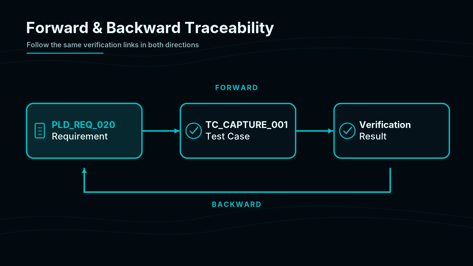
This bidirectional relationship helps identify both unverified requirements and verification activities that lack a clear requirement justification.
3. Linking Requirements to RTL Design
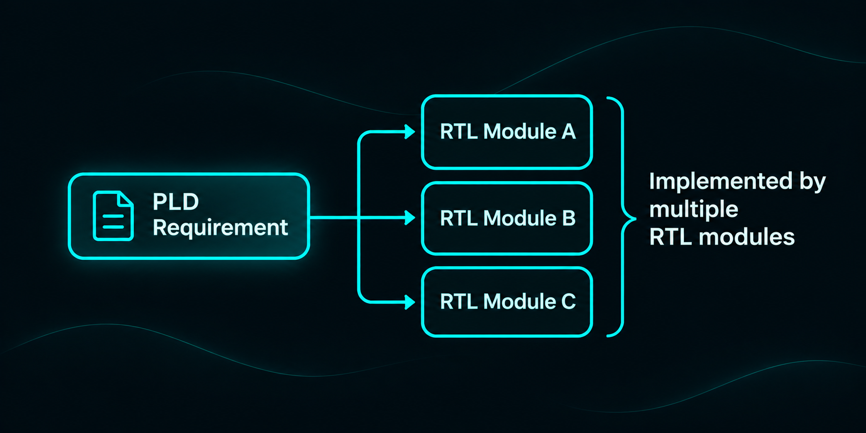
In FPGA development, a requirement may be implemented by a single RTL module or across multiple modules.
One Requirement May Map to Multiple Design Elements
Consider an FPGA that receives video data and transfers it through a processing pipeline.
PLD_REQ_030: When pixel_valid_in is sampled high at a rising edge of clk_video, the FPGA shall present the corresponding pixel at pixel_out and assert pixel_valid_out exactly three clock cycles later, provided reset remains inactive.
Suppose this functionality is implemented using three RTL modules:
| Design Element | Responsibility |
|---|---|
video_input_register.vhd | Captures the incoming pixel data and validity information. |
pixel_pipeline.vhd | Transfers the pixel data and validity information through the pipeline. |
video_output_formatter.vhd | Drives the corresponding output data and validity signal. |
In this example, a single requirement is implemented across multiple design elements. Therefore, the traceability relationship should include all relevant modules involved in implementing the requirement.
The opposite situation is also possible. A single RTL module may implement multiple requirements related to initialization, data processing, reset handling, or output control.
Choosing the Right Level of Traceability
Traceability should be detailed enough to identify where a requirement is implemented without creating unnecessary maintenance overhead.
For example, linking every PLD requirement to a single top-level RTL file provides limited information about where individual functions are implemented. On the other hand, establishing links to every HDL statement may introduce excessive complexity.
A practical approach is to establish traceability at the RTL module level and refine the links when additional detail is necessary.
However, a traceability link identifies where a requirement is implemented; it does not, by itself, demonstrate that the implementation is correct.
4. Linking Requirements to Verification Test Cases
In a requirements-based verification approach, each PLD requirement should be linked to appropriate verification test cases and procedures.
Consider the following requirements from our previous article:
- PLD_REQ_010: The
cmd_ackoutput shall assert high within 4 clock cycles after a valid command is accepted. - PLD_REQ_011: Once asserted,
cmd_ackshall deassert low on the next rising edge ofclk_50. - PLD_REQ_012: When
reset_nis low,cmd_ackshall be low regardless of the command inputs.
An example verification traceability table is shown below:
| PLD Requirement | Verification Test Case | Verification Objective |
|---|---|---|
| PLD_REQ_010 | TC_CMD_001 | Verify command acknowledgment latency |
| PLD_REQ_011 | TC_CMD_002 | Verify acknowledgment pulse duration |
| PLD_REQ_012 | TC_RST_001 | Verify acknowledgment behavior during reset |
A single test case may cover multiple requirements, while one requirement may require several test cases to verify its behavior under different operating conditions.
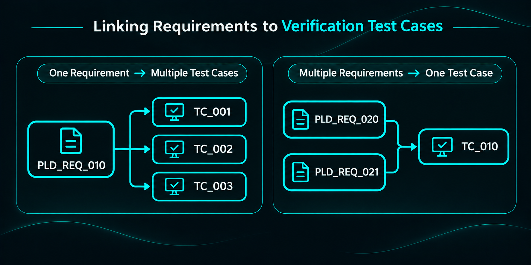
These conditions may include both normal operation and robustness scenarios.
For example, a normal test case might verify acknowledgment behavior during an uninterrupted command transaction. A robustness test case might verify the expected behavior when reset is applied during an active command transaction.
Therefore, depending on the project’s verification methodology, verification activities may be organized into Normal Test Cases and Robustness Test Cases.
Robustness tests focus on verifying expected behavior under abnormal, boundary, and worst-case operating conditions. The expected behavior under these conditions should be defined by requirements rather than assumptions about the RTL implementation.
Normal and robustness verification approaches, including how to develop requirements-based test cases, will be discussed in more detail in our next article.
Linking Test Cases to Verification Results
Defining a test case does not necessarily mean that the associated requirement has been successfully verified.
Verification traceability should also extend to verification evidence, such as simulation results, test reports, or review records.
For example:
PLD_REQ_010 → TC_CMD_001 → Verification Result
The verification result should indicate whether the test passed, failed, or has unresolved issues. The relevant design and verification configuration should also be identified.
Traceability Completeness vs. Verification Coverage
Establishing traceability links is only part of the process. The correctness and completeness of these relationships must also be evaluated.
Consider a requirement stating that the FPGA shall generate a command acknowledgment within four clock cycles after accepting a command.
Suppose a test case only checks whether cmd_ack eventually asserts high, without checking the specified latency.
The test case may be linked to the correct requirement, but it does not fully verify the required behavior.
This example highlights an important distinction:
- Traceability Completeness: Evaluates whether the necessary relationships between requirements, design elements, and verification records have been established.
- Verification Coverage: Evaluates whether the verification activities adequately cover the behaviors and conditions specified by the requirements.
A complete traceability matrix does not automatically imply complete verification coverage.
Similarly, HDL code coverage metrics, such as statement, branch, and toggle coverage, indicate which portions of the RTL design have been exercised. However, these metrics alone do not demonstrate that all requirements have been adequately verified.
Therefore, traceability reviews should evaluate not only whether links exist but also whether the associated verification activities correctly and completely address the requirements.
5. Derived Requirements and Missing Links
As discussed in our previous article, PLD requirements may be directly allocated, refined or decomposed from higher-level requirements, or derived during development.
Directly allocated and refined requirements should maintain traceability to their appropriate higher-level sources. Derived requirements, however, may originate from design decisions that introduce behavior not explicitly defined by higher-level requirements.
For example, consider an FPGA that continuously receives and processes video frames.
During detailed design, engineers identify a potential issue: if reset is released in the middle of an incoming frame, forwarding the remaining pixels could result in an incomplete frame appearing at the output.
To prevent this behavior, the design team decides that incomplete frames following reset should not be forwarded to the downstream interface.
If this behavior is neither specified nor implied by the higher-level requirements, the following derived PLD requirement may be introduced:
PLD_REQ_031: Following the release of reset_n during an active input frame, the FPGA shall keep video_out_valid low until the start of the next input frame, indicated by frame_start_in at a rising edge of clk_video.
This requirement defines the expected FPGA output behavior under a specific operating condition without prescribing the architecture or RTL implementation used to achieve it.
The requirement’s origin and rationale should be documented, the requirement should be validated, and appropriate links to design and verification records should be established. Whether the requirement is classified as derived or as a refinement depends on the content of the higher-level requirements.
What Do Missing Traceability Links Tell Us?
During traceability reviews, several situations may indicate potential gaps in the development process:
- A PLD requirement without a design link: The requirement may not have been implemented, or the corresponding relationship may not have been documented.
- A PLD requirement without a verification link: An appropriate verification activity may not have been defined.
- An RTL design element without a justified requirement relationship: The design may contain additional functionality or undocumented design decisions.
- A requirement without a higher-level source or documented derivation rationale: The origin of the requirement may require further investigation.
Not every missing link necessarily indicates a design error. For example, derived requirements may not have a direct higher-level requirement link. Likewise, not every HDL implementation detail requires a separate functional requirement.
The goal is not simply to fill empty cells in a traceability matrix, but to identify and resolve unjustified gaps.
6. Traceability in Change Management
During FPGA development, requirements may change due to system-level updates, architectural decisions, or verification findings. Traceability helps identify which design elements and verification activities may be affected by these changes.
Consider a modification to our previous command acknowledgment requirement.
The original requirement states:
PLD_REQ_010: The cmd_ack output shall assert high within 4 clock cycles after a valid command is accepted.
Suppose a new system-level timing constraint requires the maximum acknowledgment latency to be reduced from four clock cycles to two.
This change may affect not only the requirement itself but also the associated design and verification activities.
Traceability relationships help engineers identify:
- Higher-level requirements: Which system or CBA requirement introduced the new timing constraint?
- RTL design elements: Which modules implement the command acknowledgment logic, and which may need modification?
- Verification test cases: Which procedures contain the original four-cycle acceptance criterion and need to be updated?
- Verification results: Which results were obtained against the previous requirement revision and may no longer provide sufficient verification evidence?
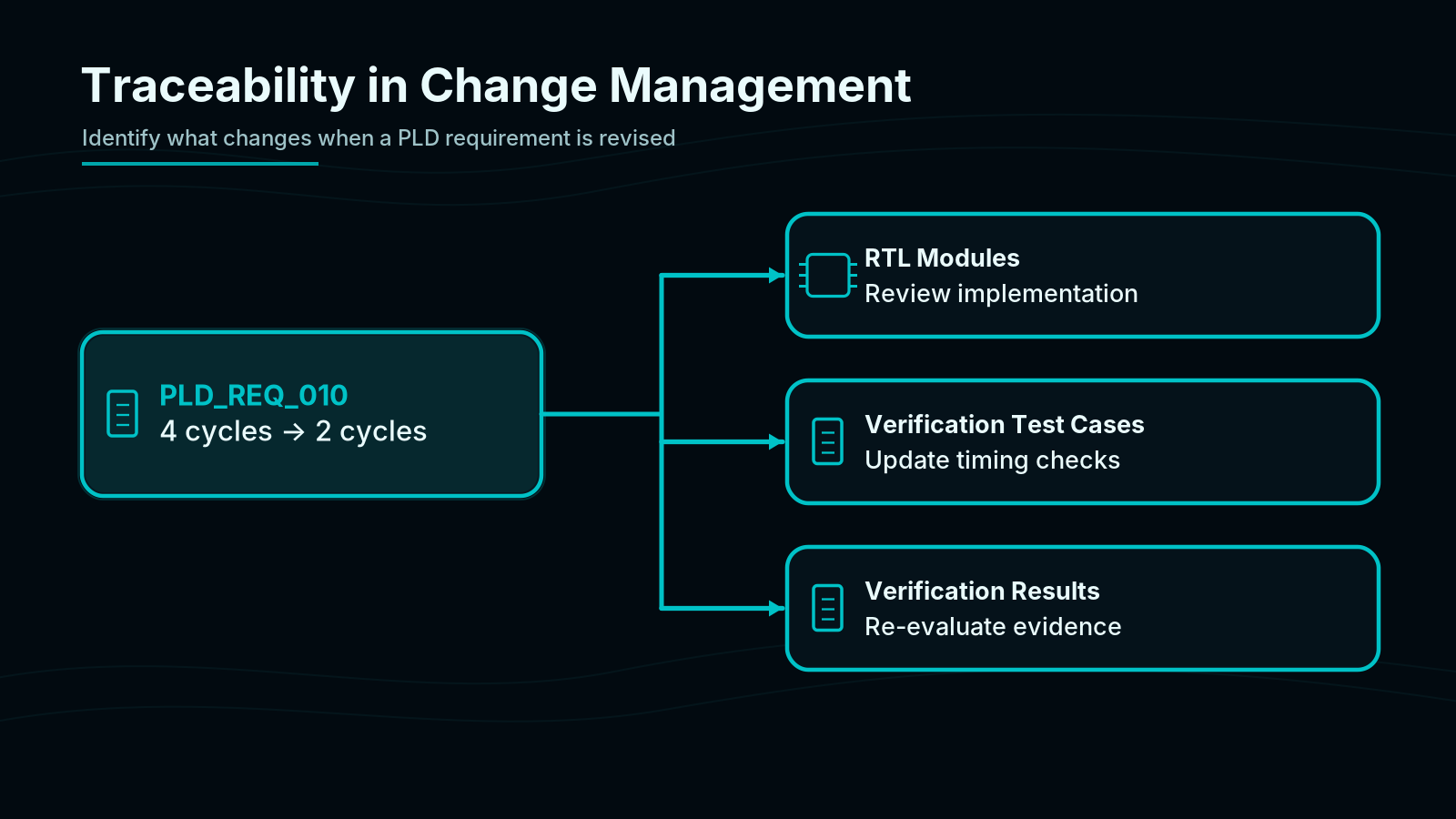
These relationships support a more focused impact analysis. Backward traceability can also help determine whether design modifications introduce additional behavior that needs to be captured in new requirements.
Traceability and Configuration Management
Requirements, RTL files, verification procedures, and results evolve through multiple revisions during development. Therefore, traceability relationships must refer to the correct versions of the associated files and documents.
For example, a successful simulation result obtained using an earlier RTL revision should not automatically be considered valid verification evidence for a modified design.
Controlled baselines, revision information, and change records help ensure that traceability remains current and valid throughout development.
Requirements management tools such as IBM DOORS can support the creation and maintenance of these relationships. For smaller projects, structured traceability matrices may also be used, provided that links and revisions are consistently managed.
7. Where DO-254 Fits into Traceability
Traceability plays an important role in the development of safety-critical airborne hardware.
DO-254 Section 10.4.1 addresses hardware traceability data and the relationships between requirements, detailed design, implementation, and verification information.
AMC 20-152A provides additional clarification through its development assurance objectives.
Two objectives are particularly relevant:
Objective CD-4 — Detailed Design Review
For DAL A and B hardware, this objective includes reviewing traceability between custom device requirements and detailed design to demonstrate that the design covers the requirements and is consistent with the conceptual design and applicable design standards.
For DAL C hardware, the objective instead addresses demonstrating compliance with hardware design standards, without prescribing the same requirements-to-detailed-design traceability review.
Objective CD-6 — Review of Verification Cases and Procedures
This objective addresses reviewing verification cases and procedures to confirm that they are appropriate for the requirements to which they trace and that the requirements are correctly and completely covered.
These objectives demonstrate that traceability involves more than maintaining a list of requirement IDs and associated file names. The correctness and adequacy of the established relationships must also be evaluated.
However, traceability should not be viewed solely as a certification activity. Even in FPGA projects outside the scope of DO-254, it supports more effective management of design and verification activities.
Closing the Loop
Traceability is not simply about creating links between requirements, design, and verification documents. It also requires keeping these relationships correct, meaningful, and up to date.
In FPGA projects, an effective traceability approach helps engineers identify where requirements are implemented and how they are verified, while also making it easier to evaluate the impact of changes.
However, linking a requirement to a verification test case does not necessarily mean that the requirement has been adequately verified.
In our next article, Requirements-Based Verification in FPGA Projects, we will explore how verification test cases are developed from requirements, including normal and robustness testing, and how verification coverage can be evaluated.
Talk to us: info@run-x.com | www.run-x.com